Beverage Package and a Method of Packaging a Beverage Containing Gas in Solution
Beverage Package and a Method of Packaging a Beverage Containing Gas in Solution
US4832968
Folder:
Year:
Abstract:
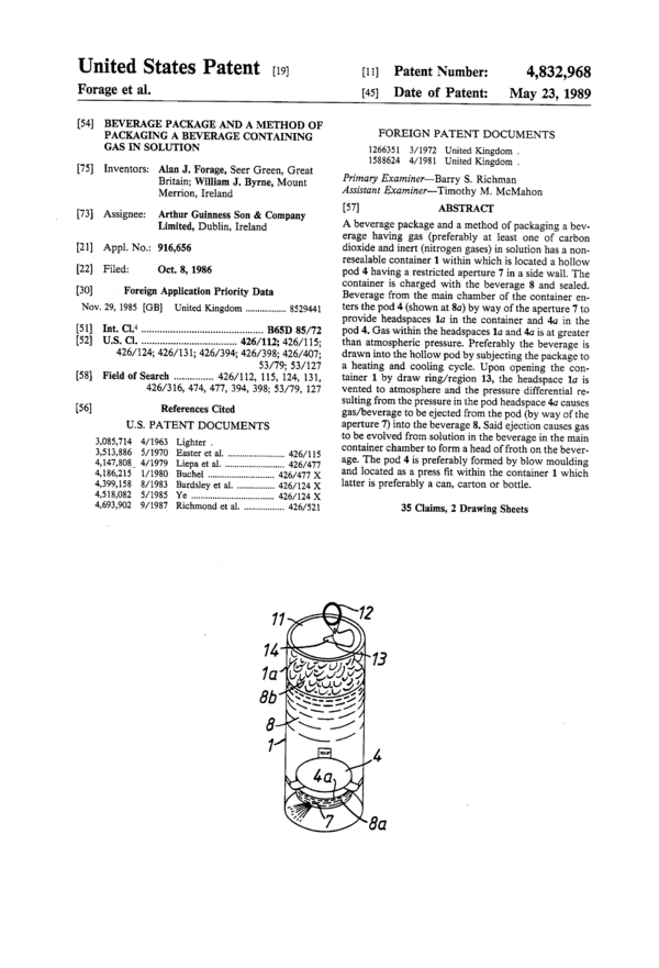
A beverage package and a method of packaging a beverage having gas (preferably at least one of carbon dioxide and inert (nitrogen gases) in solution has a non-resealable container 1 within which is located a hollow pod 4 having a restricted aperture 7 in a side wall. The container is charged with the beverage 8 and sealed. Beverage from the main chamber of the container enters the pod 4 (shown at 8a) by way of the aperture 7 to provide headspaces 1a in the container and 4a in the pod 4. Gas within the headspaces 1a and 4a is at greater than atmospheric pressure. Preferably the beverage is drawn into the hollow pod by subjecting the package to a heating and cooling cycle. Upon opening the container 1 by draw ring/region 13, the headspace 1a is vented to atmosphere and the pressure differential resulting from the pressure in the pod headspace 4a causes gas/beverage to be ejected from the pod (by way of the aperture 7) into the beverage 8. Said ejection causes gas to be evolved from solution in the beverage in the main container chamber to from a head of froth on the beverage. The pod 4 is preferably formed by blow moulding and located as a press fit within the container 1 which latter is preferably a can, carton or bottle.
Type of document:
Language:
United States Patent [191
Forage et al.
[54] BEVERAGE PACKAGE AND A METHOD OF
PACKAGING A BEVERAGE CONTAINING
GAS IN SOLUTION
[75] Inventors: Alan J. Forage, Seer Green, Great
Britain; William J. Byrne, Mount
Merrion, Ireland
[73] Assignee: Arthur Guinness Son & Company
Limited, Dublin, Ireland
[21] Appl. No.: 916,656
[22] Filed: Oct. 3, 1986
[30] Foreign Application Priority Data
Nov. 29, 1985 [GB] United Kingdom ............... .. 8529441
[51] Int. Cl.4 ............................................ .. B65D 85/72
[52] U.S. Cl. ................................. 426/112; 426/115;
426/124; 426/131; 426/394; 426/ 398; 426/407;
53/79; 53/127
[58] Field of Search ............. .. 426/112, 115, 124, 131,
426/316, 474, 477, 394, 398; 53/79, 127
[56] References Cited
U.S. PATENT DOCUMENTS
3,085,714 4/1963 Lighter .
3,513,886 5/1970 Easter et al. ...................... .. 426/115
4,147,808’ 4/1979 Liepa et al. . . . . . . . .. 426/477
4,186,215 1/1980 Buchel ............. .. . 426/477 X
4,399,158 8/1983 Bardsley et al. 426/124 X
4,518,082 5/1985 Ye ........................ .. . 426/124 X
4,693,902 9/1987 Richmond et al. . .............. .. 426/521
[11] Patent Number:
[45] Date of Patent:
4,832,968
May 23, 1989
FOREIGN PATENT DOCUMENTS
1266351 3/1972 United Kingdom .
1588624 4/1981 United Kingdom.
Primary Examiner—Barry S. Richman
Assistant Examiner-—Timothy M. McMahon
[57] ABSTRACI‘
A beverage package and a method of packaging a bev-
erage having gas (preferably at least one of carbon
dioxide and inert (nitrogen gases) in solution has a non-
resealable container 1 within which is located a hollow
pod 4 having a restricted aperture 7 in a side wall. The
container is charged with the beverage 8 and sealed.
Beverage from the main chamber of the container en-
ters the pod 4 (shown at 8a) by way of the aperture 7 to
provide headspaces la in the container and 4a in the
pod 4. Gas within the headspaces la and 4a is at greater
than atmospheric pressure. Preferably the beverage is
drawn into the hollow pod by subjecting the package to
a heating and cooling cycle. Upon opening the con-
tainer 1 by draw ring/region 13, the headspace la is
vented to atmosphere and the pressure differential re-
sulting from the pressure in the pod headspace 4a causes
gas/beverage to be ejected from the pod (by way of the
aperture 7) into the beverage 8. Said ejection causes gas
to be evolved from solution in the beverage in the main
container chamber to form a head of froth on the bever-
age. The pod 4 is preferably formed by blow moulding
and located as a press fit within the container 1 which
latter is preferably a can, carton or bottle.
35 Claims, 2 Drawing Sheets
U.S. Patent May 23,1989 Sheet 1 of2 4,832,968
U.S. Patent May 23,1989 Sheet 2 of 2 4,832,968
4,832,968
1
BEVERAGE PACKAGE AND A METHOD OF
PACKAGING A BEVERAGE CONTAINING GAS IN
SOLUTION
TECHNICAL FIELD AND BACKGROUND ART
This invention relates to a beverage package and a
method of packaging a beverage containing gas in solu-
tion. The invention more particularly concerns bever-
ages containing gas in solution and packaged in a sealed,
non-resealable, container which, when opened for dis-
pensing or consumption, permits gas to be evolved or
liberated from the beverage to form, or assist in the
formation of, a head or froth on the beverage. The
beverages to which the invention relates may be alco-
holic or non-alcoholic; primarily the invention was
developed for fermented beverages such as beer, stout,
ale, lager and cider but may be applied with advantage
to so-called soft drinks and beverages (for example fruit
juices, squashes, colas, lemonades, milk and milk based
drinks and similar type drinks) and to alcoholic drinks
(for example spirits, liqueurs, wine or wine based drinks
and similar).
It is recognised in the beverage dispensing and pack-
aging art that the characteristics of the head of froth
which is provided on the beverage by the liberation of
gas from the beverage immediately prior to consump-
tion are an important consideration to the consumers
enjoyment of the product and are therefore of commer-
cial importance. Conventionally beverages of the type
discussed above containing gas in solution and pack-
aged in a non-resealable container (such as a can, bottle
or carton) provide a headspace in the container within
which gas is maintained under pressure. Upon opening
of the package, the headspace gas is vented to atmo-
sphere and the beverage is usually poured into a drink-
ing vessel. During such dispensing of the beverage it is
usual for gas in solution to be liberated to create the
froth or head. It is generally recognised that when dis-
pensing a beverage as aforementioned, the gas is liber-
ated as a result of the movement of the beverage over a
surface having so-called gas nucleation or active sites
which may be the wall of the drinking vessel into which
the beverage is poured. There is therefore a distinct
possibility with conventional beverage packages that
upon opening of the container after storage and until the
beverage is poured therefrom, the beverage will have
little or no froth or head—such a headless beverage is
usually regarded by the consumer as somewhat unat-
tractive and unappealing especially where the beverage
is to be drunk directly from the container. Admittedly it
may be possible to develop a head or froth within the
container by agitating or shaking the package (so that
the movement of the beverage over the interior surface
of the container causes the liberation of the gas in solu-
tion) but this is clearly inconvenient once the container
is opened and is inadvisable if the package is shaken
immediately prior to opening as the contents tend to
spray or spurt on opening.
There is therefore a need for a beverage package and
a method of packaging a beverage containing gas in
solution by which the beverage is packaged in a non-
resealable container so that when the container is
opened gas is liberated from the beverage to form or
assist in the formation of a head or froth without the
necessity of an external influence being applied to the
package; it is an object of the present invention to sat-
10
15
20
25
30
35
45
50
55
65
2
isfy this need in a simple, economic and commercially
viable manner.
STATEMENTS OF INVENTION AND
ADVANTAGES
According to the present invention there is provided
a beverage package comprising a sealed, non-resealable,
container having a primary chamber containing bever-
age having gas in solution therewith and forming a
primary headspace comprising gas at a pressure greater
than atmospheric; a secondary chamber having a vol-
ume less than said primary chamber and which commu-
nicates with the beverage in said primary chamber
through a restricted orifice, said secondary chamber
containing beverage derived from the primary chamber
and having a secondary headspace therein comprising
gas at a pressure greater than atmospheric so that the
pressures within the primary and secondary chambers
are substantially at equilibrium, and wherein said pack-
age is openable, to open the primary headspace to atmo-
spheric pressure and the secondary chamber is arranged
so that on said opening the pressure differential caused
by the decrease in pressure at the primary headspace
causes at least one of the beverage and gas in the sec-
ondary chamber to be ejected by way of the restricted
orifice into the beverage of the primary chamber and
said ejection causes gas in the solution to be evolved
and form, or assist in the formation of, a head of froth on
the beverage.
Further according to the present invention there is
provided a method of packaging a beverage having gas
in solution therewith which comprises providing a con-
tainer with a primary chamber and a secondary cham-
ber of which the volume of the secondary chamber is
less than that of the primary chamber and with a re-
stricted orifice through which the secondary chamber
communicates with the primary chamber, and charging
and sealing the primary chamber with the beverage to
contain the gas in solution and to form a primary head-
space in the primary chamber, and charging the second-
ary chamber with beverage derived from the primary
chamber by way of said restricted orifice to form a
secondary headspace in the secondary chamber
whereby the pressures in both the primary and second-
ary chambers are at equilibrium and gaseous pressures
in both the primary and secondary headspaces are at a
pressure greater than atmospheric so that, when the
container is broached to open the primary headspace to
atmospheric pressure, the pressure differential caused
by the decrease in pressure at the primary headspace
causes at least one of the beverage and gas in the sec-
ondary chamber to be ejected into the beverage of the
primary chamber by way of said restricted orifice and
the said ejection causes gas to be evolved from solution
in the beverage in the primary chamber to form, or
assist in the formation of, a head of froth on the bever-
age.
The present invention is applicable to a wide range of
beverages of the type as previously discussed and where
those beverages contain gas in solution which gas is
intended to be liberated to form or assist in the forma-
tion of the head or froth on the beverage. Understand-
ably the gas in solution must not detract from, and
should preferably enhance the characteristics required
of the beverage and be acceptable for use with food
products; preferably therefore the gas is at least one of
carbon dioxide and inert gases (by which latter term is
4,832,968
3
included nitrogen) although it is to be realised that other
gases may be appropriate.
The present invention was primarily developed for
the packaging of fermented beverages such as beer, ale,
stout, lager and cider where among the desirable quali-
ties sought in a head are a consistent and regular, rela-
tively fine, bubble size; a bubble structure which is
substantially homogeneous so that the head is not
formed with large irregularly shaped and random gaps;
the ability for the head or bubble structure to endure
during a reasonable period over which it is likely to be
consumed, and a so-called “mouth-feel” and flavour
which may improve the enjoyment of the beverage
during consumption and not detract from the desirable
flavour characteristics required of the beverage. These
desirable qualities are of course equally applicable to
non-fermented beverages, for example with so-called
soft drinks. Conventionally, beverages of the type to
which the invention relates are packaged in a non-
resealable container which when opened totally vents
the headspace to atmosphere, contain carbon dioxide in
solution and it is the liberation of the carbon dioxide on
opening of the package and dispensing of the beverage
into a drinking vessel which creates the froth or head;
however, the head so formed has very few of the afore-
mentioned desirable qualities—in particular it is usually
irregular, lacks homogeneity and has very little endur-
ance so that there is a tendency for it to collapse after a
short period. It has been known for approximately 25
years and as discussed in our G.B. Pat. No. 876,628, that
beverages having in solution a mixture of carbon diox-
ide gas and inert gas (such as nitrogen or argon) will,
when dispensed in a manner whereby the mixed gases
are caused to evolve to develop the head or foam from
small bubbles containing the mixture of carbon dioxide
and, say, nitrogen gases, provide the desirable qualities
for the head as previously discussed. Commercially the
formation of the head by the use of mixed gases as afore-
mentioned has been widely employed in the dispensing
of beverage in a draught system and on demand from a
bulk container (such as a keg or barrel) where the gases
are caused to evolve by subjecting the beverage to
intense shear forces in passing it under pressure through
a set of small holes. Beverages, particularly stout, hav-
ing a mixture of carbon dioxide and nitrogen gases in
solution and dispensed in draught using the aforemen-
tioned technique have met with considerable commer-
cial success and it was soon realised that there was a
10
15
20
25
30
35
45
need to make available for consumption a similar bever- ’
age derived from a small non-resealable container suit-
able for shelf storage and retail purposes.
Research has indicated that to achieve the initiation
of a head on a beverage containing carbon dioxide and
inert gas such as nitrogen in solution it is necessary to
provide so-called “active sites” which are regions
where the beverage is subjected to a high local strain
(such a strain being higher than the cohesive force of
the beverage). In these conditions the beverage prefers
to generate a bubble of mixed gases instead of “bending
around” the active site. It was found that an active site
could be solid, liquid or gas such as granules, restrictor
holes, rapid streams of liquid or bubbles and the like. It
was also found that ultrasonics could produce a “ghost”
active site by the formation of extreme pressure gradi-
ents. There has however been a problem in providing an
“active site” in a beverage packaged in a non-resealable
small container in a manner which is commercially and
economically acceptable. During the past 25 years con-
50
55
60
65
4
siderable expenditure has been devoted to research and
development in an attempt to overcome the aforemen-
tioned problem. For example, our G.B. Pat. No.
1,588,624 proposes initiating the evolution of mixed
carbon dioxide and nitrogen gases from a beverage by
subjecting the beverage to ultrasonic excitement, by
injecting a gas, liquid and/ or foam into the beverage by
use of a syringe-type device, or by pouring the beverage
over an excitation surface such as polystyrene granules.
Although these latter proposals were successful in
achieving the desired head formation, the necessity to
use ancilliary apparatus had commercial disadvantages
(for example, it is unreasonable to expect a retail cus-
tomer to have available an ultrasonic signal generator;
also the steps required to effect initiation of the head
following opening of the beverage package involved an
inconvenient discipline and time factor). In a further
example our G.B. Pat. No. 1,266,351 relates to a non-
resealable package containing beverage having mixed
carbon dioxide and inert gases in solution; in this disclo-
sure a can or bottle has two chambers of which a larger
chamber contains the beverage while the smaller cham-
ber is charged under pressure with the mixed gases. On
opening of the can or bottle to expose the larger cham-
ber to atmosphere, its intemal pressure falls to atmo-
spheric permitting the pressurised gas in the small
chamber to jet into the beverage by way of a small
orifice between the two chambers. This jet of gas pro-
vides sufficient energy to initiate the formation of min-
ute bubbles and thereby the head from the evolution of
the mixed gases in the beverage coming out of solution.
By this proposal the small gas chamber is initially press-
urised with the mixed gases to a pressure greater than
atmospheric and from a source remote from the bever-
age; as a consequence it was found necessary, particu-
larly in the case of cans, to provide a special design of
two chambered container and an appropriate means for
sealing the smaller chamber following the charging of
that chamber with the mixed gases (such charging usu-
ally being effected, in the case of cans, by injecting the
mixed gases into the small chamber through a wall of
the can which then had to be sealed). Because of the
inconvenience and high costs involved in the develop-
ment of an appropriate two chambered container and
the special facilities required for charging the mixed
gases and sealing the container, the proposal proved
commercially unacceptable.
The container employed in the present invention will
usually be in the form of a can, bottle or carton capable
-of withstanding the internal pressures of the primary
and secondary chambers and of a size suitable for con-
ventional shelf storage by the retail trade so that, the
overall volume of the container may be, typically, 0.5
liters but is unlikely to be greater than 3 liters.
By the present invention a two chambered container
is employed as broadly proposed in G.B. Pat. No.
1,266,351; however, unlike the prior proposal the sec-
ondary chamber is partly filled with beverage contain-
ing gases in solution and the beverage in the secondary
chamber is derived wholly from the beverage in the
primary chamber so that when the contents of the pri-
mary and secondary chambers are in equilibrium (and
the primary and secondary headspaces are at a pressure
greater than atmospheric) immediately prior to broach-
ing the container to open the primary headspace to
atmosphere, the pressure differential between that in the
secondary headspace and atmospheric pressure causes
beverage in the secondary chamber to be ejected by
4,832,968
5
way of the restricted orifice into the beverage in the
primary chamber to promote the formation of the head
of froth without the necessity of any extemal influence
being applied to the package. The pressurisation of the
headspace gas in the secondary chamber is intended to
result from the evolution of gas in the sealed container
as the contents of the container come into equilibrium at
ambient or dispensing temperature (which should be
greater than the temperature at which the container is
charged and sealed). Consequently the present inven-
tion alleviates the necessity for pressurising the second-
ary chamber from a source extemally of the container
so that the secondary chamber can be formed as a sim-
ple envelope or hollow pod of any convenient shape
(such as cylindrical or spherical) which is located as a
discrete insert within a conventional form of can, bottle
or carton (thereby alleviating the requirement for a
special structure of can or bottle as envisaged in G.B.
Pat. No. 1,266,351).
Although the head or froth formed by pouring
wholly carbonated beverages tends to lack many of the
desirable qualities required of a head as previously dis-
cussed; our tests have indicated that by use of the pres-
ent invention with wholly carbonated beverages (where
the head is formed by injection of beverage from the
secondary chamber into the primary chamber) the re-
sultant head is considerably tighter or denser than that
achieved solely by pouring and as such will normally
have a greater life expectancy.
The beverage is preferably saturated or supersatu-
rated with the gas (especially if mixed carbon dioxide
and inert gases are employed) and the primary chamber
charged with the beverage under a counterpressure and
at a low temperature (to alleviate gas losses and, say, at
a slightly higher temperature than that at which the
beverage freezes) so that when the container is sealed
(which may be achieved under atmospheric pressure
using conventional systems such as a canning or bot-
tling line), the pressurisation of the primary and second-
ary headspaces is achieved by the evolution of gas from
the beverage within the primary and secondary cham-
bers as the package is handled or stored at an ambient or
dispensing temperature (greater than the charging tem-
perature) and the contents of the container adopt a state
of equilibrium. Following the sealing of the container,
the package may be subjected to a heating and cooling
cycle, conveniently during pasteurisation of the bever-
age.
The restricted orifice through which the primary and
secondary chambers communicate is conveniently
formed by a single aperture in a side wall of the second-
ary chamber and such an aperture should have a size
which is sufficiently great to alleviate “clogging” or its
obturation by particles which may normally be ex-
pected to occur within the beverage and yet be re-
stricted in its dimensions to ensure that there is an ade-
quate jetting effect in the ejection of the beverage there-
through from the secondary chamber into the primary
chamber to promote the head formation upon opening
of the container. The restricted orifice may be of any
profile (such as a slit or a star shape) but will usually be
circular; experiments have indicated that a restricted
orifice having a diameter in the range of 0.02 to 0.25
centimeters is likely to be appropriate for fermented
beverages (the preferred diameter being 0.061 centime-
ters). It is also preferred that when the package is posi-
tioned in an upstanding condition in which it is likely to
be transported, shelf stored or opened, the restricted
5
l0
15
20
25
30
35
45
50
55
60
65
6
orifice is located in an upwardly extending side wall or
in a bottom wall of the secondary chamber and prefera-
bly at a position slightly spaced from the bottom of the
primary chamber. When the contents of the sealed
package are in equilibrium and the package is in an
upstanding condition as aforementioned, the restricted
orifice is located below the depth of the beverage in the
secondary chamber so that on opening of the container
the pressure of gas in the secondary headspace initially
ejects beverage from that chamber into the beverage in
the primary chamber to promote the head formation.
Such ejection of beverage through the restricted orifice
provides a greater efficiency in the development of the
head in a liquid supersaturated with gas than will the
ejection of gas alone through the restricted orifice; the
reason for this is that the restricted orifice provides a
very active site which causes the beverage to “rip itself
apart” generating extremely minute bubbles which
themselves act as active sites for the beverage in the
primary chamber, these extremely minute bubbles leave
“vapour trails” of larger initiated bubbles which in turn
produce the head. Since the extremely minute bubbles
are travelling at relatively high speed during their injec-
tion into the beverage in the primary chamber, they not
only generate shear forces on the beverage in that
chamber but the effect of each such bubble is distributed
over a volume of beverage much larger than the imme-
diate surroundings of ' an otherwise stationary bubble.
A particular advantage of the present invention is
that prior to the container being charged with beverage
both the primary and secondary chambers can be at
atmospheric pressure and indeed may contain air. How-
ever, it is recognized that for many beverages, particu-
larly a fermented beverage, prolonged storage of the
beverage in contact with air, especially oxygen, is unde-
sirable as adversely affecting the characteristics of the
beverage. To alleviate this possibility the secondary
chamber may initially be filled with a “non-contami-
nant” gas such as nitrogen (or other inert gas or carbon
dioxide) which does not adversely affect the character-
istics of the beverage during prolonged contact there-
with. The secondary chamber may be filled with the
non-contaminant gas at atmospheric pressure or slightly
greater (to alleviate the inadvertent intake of air) so that
when the container is charged with the beverage, the
non-contaminant gas will form part of the pressurised
headspace in the secondary chamber. As previously
mentioned, the secondary chamber may be formed by
an envelope or hollow pod which is located as a dis-
crete insert within a conventional form of can, bottle or
carton and such a discrete insert permits the secondary
chamber to be filled with the non-contaminant gas prior
to the envelope or pod being located within the can,
bottle or carton. A convenient means of achieving this
latter effect is by blow moulding the envelope or pod in
a food grade plastics material using the non-contami-
nant gas as the blowing medium and thereafter sealing
‘the envelope or pod to retain the non-contaminant gas
therein; immediately prior to the pod or envelope being
inserted into the can, bottle or carton, the restricted
orifice can be formed in a side wall of the pod or enve-
lope (for example by laser boring). Immediately prior to
the container being sealed it is also preferable to remove
air from the primary headspace and this may be
achieved using conventional techniques such as filling
the headspace with froth or fob developed from a
source remote from the container and having character-
istics similar to those of the head which is to be formed
4,832,968
7
from the beverage in the container; charging the pri-
mary chamber with the beverage in a nitrogen or other
inert gas atmosphere so that the headspace is filled with
that inert gas or nitrogen; dosing the headspace with
liquid nitrogen so that the gas evolved therefrom expels
the air from the headspace, or by use of undercover
gassing or water jetting techniques to exclude air.
The secondary chamber may be charged with bever-
age from the primary chamber at ambient temperature.
It is possible to ensure that the secondary chamber is
efficiently charged by applying an auxilliary pressure to
the headspace of the primary chamber (relative to the
headspace in the secondary chamber) and allowing the
pressures in the container to equilibriate after the pri-
mary chamber has been sealed. An efficient means of
applying an auxiliary pressure is by use of the aforemen-
tioned liquid nitrogen dosing where a dose of liquid
nitrogen is applied to the headspace of the beverage in
the primary chamber immediately before that chamber
is sealed so that, following sealing, the development of
pressure in the primary headspace (assisted by the evo-
lution of nitrogen gas from the dosing) forces beverage
from the primary chamber into the secondary chamber
(by way of the restricted orifice) until a state of equilib-
rium is reached for the contents of the container.
Although the secondary chamber may be constructed
as an integral part of the container, for the reasons dis-
cussed above and also convenience of manufacture, it is
preferred that the secondary chamber is formed as a
discrete insert which is simply deposited or pushed into
a conventional form of can, bottle or carton. With cans
or cartons such an insert will not be visible to the end
user and many bottled beverages are traditionally mar-
keted in dark coloured glass or plastics so that the insert
is unlikely to adversely affect the aesthetics of the pack-
age. The discrete insert may be suspended or float in the
beverage in the primary chamber provided that the
restricted orifice is maintained below the surface of the
beverage in the primary chamber on opening of the
container; for example the insert may be loaded or
weighted to appropriately orientate the position of the
restricted orifice. Desirably however the insert is re-
strained from displacement within the outer container
of the package and may be retained in position, for
example at the bottom of the outer container, by an
appropriate adhesive or by mechanical means such as
projections on the package which may flex to abut and
grip a side wall of the outer container or which may
engage beneath an intemal abutment on the side wall of
the outer container.
DRAWINGS
One embodiment of the present invention as applied
to the packaging of a fermented beverage such as stout
in a can will now be described, by way of example only,
with reference to the accompanying illustrative draw-
ings, in which:
FIGS. 1 to 4 diagrammatically illustrate the progres-
sive stages in the formation of the beverage package in
a canning line, and
FIG. 5 diagrammatically illustrates the effect on
opening the beverage package prior to consumption of
the beverage and the development of the head of froth
on the beverage.
DETAILED DESCRIPTION OF DRAWINGS
The present embodiment will be considered in rela-
tion to the preparation of a sealed can containing stout
10
15
20
25
30
35
45
50
55
60
65
8
having in solution a mixture of nitrogen and carbon
dioxide gases, the former preferably being present to the
extent of at least 1.5% vols/vol and typically in the
range 1.5% to 3.5% vols/vol and the carbon dioxide
being present at a considerably lower level than the
amount of carbon dioxide which would normally be
present in conventional, wholly carbonated, bottled or
canned stout and typically in the range 0.8 to 1.8 vols/-
vol (1.46 to 3.29 grams/liter). For the avoidance of
doubt, a definition of the term “vols/vol” is to be found
in U.S. Pat. No. 4,279,938 and may be taken as “the
number of volumes of gas which are dissolved in a unit
volume of the beverage, said volumes of gas being de-
termined at a pressure of 760 millimeters of mercury
and at a temperature of 15.6“ C.”.
The stout is to be packaged in a conventional form of
cylindrical can (typically of aluminum alloy) which, in
the present example, will be regarded as having a capac-
ity of 500 milliliters and by use of a conventional form
of filling and canning line appropriately modified as will
hereinafter be described. A cylindrical shell for the can
1 having a sealed base 2 and an open top 3 is passed in
an upstanding condition along the line to a station
shown in FIG. 1 to present its open top beneath a stack
of hollow pods 4. Each pod 4 is moulded in a food grade
plastics material such as polypropylene to have a short
(say 5 millimeters) hollow cylindrical housing part 5
and a circumferentially spaced array of radially out-
wardly extending flexible tabs or lugs 6. The pods 4 are
placed in the-stack with the chamber formed by the
housing part 5 sealed and containing nitrogen gas at
atmospheric pressure (or at pressure slightly above
atmospheric); conveniently this is achieved by blow
moulding the housing part 5 using nitrogen gas. The
volume within the housing part 5 is approximately 15
milliliters. At the station shown in FIG. 1 the bottom
pod 4 of the stack is displaced by suitable means (not
shown) into the open topped can 1 as shown. However,
immediately prior to the pod 4 being moved into the can
1 a small (restricted) hole 7 is bored in the cylindrical
side wall of the housing part 5. In the present example,
the hole 7 has a diameter in the order of 0.61 millimeters
and is conveniently bored by a laser beam generated by
device 7a (although the hole could be formed by punch-
ing or drilling). The hole 7 is located towards the bot-
tom of the cylindrical chamber within the housing part
5. Since the hollow pod 4 contains nitrogen gas at atmo-
spheric pressure (or slightly higher) it is unlikely that air
will enter the hollow pod through the hole 7 during the
period between boring the hole 7 and charging of the
can 1 with stout (thereby alleviating contamination of
the stout by an oxygen content within the hollow pod
4).
The hollow pod 4 is pressed into the can 1 to be
seated on the base 2. Conventional cans 1 have a domed
base 2 (shown by the section 2a) which presents a con-
vex internal face so that when the pod 4 abuts this face
a clearance is provided between the hole 7 and the
underlying bottom of the chamber within the can 1. It
will be seen from FIG. 1 that the diameter of the hous-
ing part 5 of the pod 4 is less than the internal diameter
of the can 1 while the diameter of the outermost edges
of the lugs 6 is greater than the diameter of the can 1 so
that as the pod 4 is pressed downwardly into the can,
the lugs 6 abut the side wall of the can and flex up-
wardly as shown to grip the can side wall and thereby
restrain the hollow pod from displacement away from
the base 2.
4,832,968
9
The open topped can with its pod 4 is now displaced
along the canning line to the station shown in FIG. 2
where the can is charged with approximately 4-40 milli-
liters of stout 8 from an appropriate source 9. The stout
8 is supersaturated with the mixed carbon dioxide and
nitrogen gases, typically the carbon dioxide gas being
.present at 1.5 vols/vol (2.74 grams/liter) and the nitro-
gen gas being present at 2% vols/vol. The charging of
the can 1 with the stout may be achieved in conven-
tional manner, that is under a counterpressure and at a
temperature of approximately 0° C. When the can 1 is
charged with the appropriate quantity of stout 8, the
headspace above the stout is purged of air, for example
by use of liquid nitrogen dosing or with nitrogen gas
delivered by means indicated at 10 to alleviate contami-
nation of the stout from oxygen in the headspace.
Following charging of the can 1 with stout and purg-
ing of the headspace, the can moves to the station
shown in FIG. 3 where it is closed and sealed under
atmospheric pressure and in conventional manner by a
lid 11 seamed to the cylindrical side wall of the can. The
lid 11 has a pull-ring 12 attached to a weakened tear-out
region 13 by which the can is intended to be broached
in conventional manner for dispensing of the contents.
Following sealing, the packaged stout is subjected to
a pasteurisation process whereby the package is heated
to approximately 60° C. for about 15-20 minutes and is
thereafter cooled to ambient temperature. Stout flows
from the chamber of the can into the chamber of the
pod so that when the package is at ambient temperature
the hole 7 is located below the depth of stout 8a within
the hollow pod 4.
Following.the pasteurisation process the contents of
the can 1 will stabilise in a condition of equilibrium with
a headspace la over the stout 8 in the primary chamber
of the can and a headspace 4a over the stout 8a in the
secondary chamber forced by the hollow pod 4 and in
the equilibrium condition. With the sealed can at ambi-
ent temperature (or a typical storage or dispensing tem-
perature which may be, say, 8° C.) the pressure of mixed
gases carbon dioxide and nitrogen (which largely re-
sults from the evolution of such gases from the stout) is
substantially the same in the headspaces la and 4a and
this pressure will be greater than atmospheric pressure,
typically in the order of 25lbs per square inch (1.72
bars).
The package in the condition shown in’ FIG. 4 is
typically that which would be made available for stor-
age and retail purposes. During handling it is realised
that the package may be tipped from its upright condi-
tion; in practice however this is unlikely to adversely
affect the contents of the hollow pod 4 because of the
condition of equilibrium within the can.
When the stout is to be made available for consump-
tion, the can 1 is opened by ripping out the region 13
with the pull-ring 12. On broaching the lid 11 as indi-
cated at 14 the headspace la rapidly depressurises to
atmospheric pressure. As a consequence the pressure
within the headspace 4a of the secondary chamber in
the pod 4 exceeds that in the headspace la and causes
. stout 8a in the hollow pod to be ejected by way of the
hole 7 into the stout 8 in the primary chamber of the
can. The restrictor hole 7 acts as a very “active site” to
the supersaturated stout 8a which passes therethrough
to be injected into the stout 8 and that stout is effec-
tively “ripped apart” to generate extremely minute
bubbles which themselves act as active sites for the
stout 8 into which they are injected. These minute bub-
l0
15
20
25
30
35
45
50
55
65
10
bles leave “vapour trails” of larger initiated bubbles
which develop within the headspace la a head 8b hav-
ing the previously discussed desirable characteristics.
It is appreciated that the headspace la occupies a
larger proportion of the volume of the can 1 than that
which would normally be expected in a 500 milliliter
capacity can; the reason for this is to ensure that there is
adequate volume in the headspace la for the head of
froth 8b to develop efficiently in the event, for example,
that the stout is to be consumed directly from the can
when the tear-out region 13 is removed. Normally how-
ever the stout 8 will first be poured from the can into an
open topped drinking vessel prior to consumption but
this pouring should not adversely affect the desirable
characteristics of the head of froth which will eventu-
ally be presented in the drinking vessel.
In the aforegoing embodiment the can 1 is charged
with stout 8 (from the source 9) having in solution the
required respective volumes of the carbon dioxide and
the nitrogen gases. In a modification the can 1 is
charged with stout (from source 9) having the carbon
dioxide gas only in solution to the required volume; the
2% vols/vol nitrogen gas necessary to achieve the re-
quired solution of mixed gas in the packaged stout is
derived from the liquid nitrogen dosing of the head-
space in the can.
We claim:
1. A beverage package comprising a sealed, non-
resealable, container having a primary chamber con-
taining beverage having gas in solution therewith and
forming a primary headspace comprising gas at a pres-
sure greater than atmospheric; enclosure means defin-
ing a secondary chamber having a volume less than said
primary chamber; restrictor means defining a restricted
orifice, said secondary chamber communicating with
the beverage in said primary chamber through said
restricted orifice; said secondary chamber containing
beverage supplied thereto from the beverage in the
primary chamber and having a secondary headspace
therein comprising gas at a pressure greater than atmo-
spheric so that the pressures within the primary and
secondary chambers are substantially at equilibrium;
said container is openable to expose the primary head-
space to atmospheric pressure, and wherein the second-
ary chamber is arranged so that upon opening of the
container the pressure differential caused by the de-
crease in pressure at the primary headspace causes bev-
erage in the secondary chamber to be ejected by way of
the restricted orifice into the beverage of the primary
chamber and said ejection causes gas in the solution to
be evolved and form, or assist in the formation of, a
head of froth on the beverage.
2. A package as claimed in claim 1 in which the con-
tainer has a base and is upstanding from said base and
has an openable top, and said enclosure means has an
upwardly extending side wall or a bottom wall within
which said restricted orifice is located.
3. A package as claimed in claim 1 in which the con-
tainer has a base on which the enclosure means is lo-
cated and said restricted orifice is located in an up-
wardly extending side wall of the enclosure means
spaced from said base.
4. A package as claimed in claim 1 in which the re-
stricted orifice comprises a circular aperture having a
diameter in the range of 0.02 to 0.25 centimeters.
5. A package as claimed in claim 1, wherein said
gas-containing beverage is a fermented beverage having
in solution therewith carbon dioxide in the range 0.8%
4,832,968
11
to 1.8% vols/vol and nitrogen in the range 1.5% to
3.5% vols/vol.
6. A package as claimed in claim 1 in which the bev-
erage has in solution therewith at least one of carbon
dioxide and nitrogen gas.
7. A package as claimed in claim 6 in which the bev-
erage is supersaturated with said gases.
8. A package as claimed in claim 1 wherein the enclo-
sure means comprises a hollow component inserted in
the container.
9. A package as claimed in claim 8 wherein the hol-
low component comprises a hollow moulding.
10. A package as claimed in claim 8 in which the
enclosure means floats or is suspended in the beverage
in the primary chamber and means is provided for locat-
ing the restricted orifice below the surface of the bever-
age in the primary chamber.
11. A package as claimed in claim 10 wherein said
locating means comprises a load means connected with
the enclosure means and weighted to locate the re-
stricted orifice below the surface of the beverage in the
primary chamber.
12. A package as claimed in claim 8 wherein means is
provided for retaining the enclosure means at a prede-
termined position within the container.
13. A package as claimed in claim 12 wherein the
container has a base and is upstanding from said base
and has an openable top and said enclosure means is
located at or towards the base of said container.
14. A package as claimed in claim 12 wherein the
enclosure means comprises a hollow envelope having
means thereon for retaining it within the container.
15. A package as claimed in claim 14 wherein the
retaining means comprise flexible tab means which en-
gage a side wall of the container to retain the insert.
16. A package as claimed in claim 14 in which the
hollow envelope comprises a hollow moulding and in
which ‘the container has a side wall and the moulding is
substantially cylindrical with radially extending tabs
engaging the side wall of the container.
17. A method of packaging a beverage having gas in
solution therewith which comprises providing a con-
tainer with a primary chamber and a secondary cham-
ber of which the volume of the secondary chamber is
less than that of the primary chamber and with the
means defining a restricted orifice through which the
secondary chamber communicates with the primary
chamber, and charging and sealing the primary cham-
ber with the beverage to contain the gas in solution and
to form a primary headspace in the primary chamber,
and charging the secondary chamber with beverage
supplied thereto from the primary chamber by way of
said restricted orifice to form a secondary headspace in
the secondary chamber whereby the pressures in both
the primary and secondary chambers are at equilibrium
and gaseous pressures in both the primary and second-
ary headspaces are at a pressure greater than atmo-
spheric so that, when the container is broached to open
the primary headspace to atmospheric pressure, the
pressure differential caused by the decrease in pressure
at the primary headspace causes beverage in the second-
ary chamber to be ejected into the beverage of the
secondary chamber by way of said restricted orifice and
the said ejection causes gas to be evolved from solution
in the beverage in the primary chamber to form, or
assist in the formation of, a head of froth on the bever-
age.
10
15
20
25
30
35
45
50
55
60
65
12
18. A method as claimed in claim 17 which com-
prises, prior to sealing the primary chamber, purging
the primary head space to exclude air.
19. A method as claimed in claim 17 in which the
container has a base and is upstanding from said base
and has an openable top, and said secondary chamber
has an upwardly extending side wall or a bottom wall
within which said restricted orifice is located.
20. A method as claimed in claim 17 which comprises
subjecting the sealed container to a heating and cooling
cycle.
21. A method as claimed in claim 20 in which the
heating and cooling cycle comprises heating to pasteur-
ization temperatures of the beverage.
22. A method as claimed in claim 17 in which com-
prises applying an auxiliary gas pressure to the head-
space of the primary chamber and allowing the pres-
sures within the container to equilibriate when the pri-
mary chamber is sealed.
23. A method as claimed in claim 22 which further
comprises applying the auxiliary gas pressure to the
headspace of the primary chamber as a result of liquid
nitrogen dosing prior to the primary chamber being
sealed.
24. A method as claimed in claim 17 in which the gas
comprises at least one of carbon dioxide and nitrogen
gas.
25. A method as claimed in claim 24 in which the
beverage is fermented and has in solution carbon diox-
ide in the range 0.8% to 1.8% vols/vol and nitrogen in
the range 1.5% to 3.5% vols/vol.
26. A method a claimed in claim 17 which further
comprises defming the secondary chamber by discrete
hollow enclosure means and locating said enclosure
means within the primary chamber of the container.
27. A method as claimed in claim 26 in which the
enclosure means is floated or suspended in the beverage
in the primary chamber and which further comprises
loading or weighting the enclosure means to locate the
restricted orifice below the surface of the beverage in
the primary chamber.
28. A method as claimed in claim 26 which further
comprises retaining the enclosure means at a predeter-
mined position within the container.
29. A method as claimed in claim 26 which further
comprises forming the restricted orifice in the enclosure
means by the method selected from the group consist-
ing of laser boring, drilling and punching.
30. A method as claimed in claim 26 in which the
container prior to being sealed has a base and is upstand-
ing from said base and has an open top through which
the primary chamber is charged with said beverage and
which further comprises locating the enclosure means
through said open top to provide the secondary cham-
ber within the container.
31. A method as claimed in claim 26 which further
comprises forming the hollow enclosure means having
the restricted orifice’ in a wall thereof and locating the
enclosure means within the primary chamber prior to
the charging and sealing of the primary chamber.
32. A method as claimed in claim 31 which further
comprises press fitting the enclosure means within the
container through an open top thereof so that during its
_ location the enclosure means engages with a side wall of
the container to be retained in position.
33. A method as claimed in claim 26 which further
comprises forming the enclosure means by blow mould-
mg.
4,832,968
13 14
34_ A method as Claimed in Claim 33 which further diately prior to locating the enclosure means in the
comprises blow moulding the enclosure means with gas primary Chamber‘
. . . . . 35. A method as claimed in claim 34 which further
for dissolution m the beverage so that said gas is sealed comprises Sealing Said gas in the Secondary chamber at
within the secondary chamber, and forming said re- 5 least at atmospheric pressure_
stricted orifice in the wall of the enclosure means irnme- * * * * *
10
15
20
25
30
35
45
50
55
65
UNITED STATES PATENT AND TRADEMARK OFFICE
CERTIFICATE OF CORRECTION
PATENTNO. : 4,832,968
DATED : May 23, 1989
INVENTOR(S): Alan J. Forage, et al
It is certified that error appears in the above-identified patent and that said Letters Patent is hereby
corrected as shown below:
On the title page item [73] should read -—Arthur Guinness Son &
Company (Dublin) Limited--
Signed and Sealed this
Twenty-sixth Day of February, 1991
Attest:
HARRY F. MANBECK. JR.
Attesting Oflicer Commissioner of Patents and Trademarks
Coments go here:
- Log in to post comments